|
|
NAVY DEPARTMENT
Washington, D.C. Back to page top
| Bu0rd File No. |
|
BuShips File No. |
PT/S76
(Re6b)
JOINT LETTER |
C-PT/S76-1 |
|
| C O N F I D E N T I A L |
|
November 19, 1943 |
| From: |
The Chief of the Bureau of Ordnance
The Chief of the Bureau of Ships |
| To: |
All Ships and Stations Concerned with Motor Torpedo Boat Operations. |
| |
| Subject: |
Alternative Armament of Mines for PT Boats. |
| |
| Reference: |
(a) |
Bu0rd and BuShips Joint ltr (BuOrd PT/S76, BuShips C-PT/S76(516)C-EN28/A2-11) dated 19 Jan. 1943 to All Ships and Stations Concerned with Motor Torpedo Boat Operations. |
| |
Enclosure:
(Herewith) |
(A) |
One copy of Instructions for Laying Mines from Motor Torpedo Boats dated 15 October 1943. |
1. Reference (a) is hereby cancelled.
2. In this letter the Bureau of Ordnance and the Bureau of Ships forward some practical suggestions and technical information for use by personnel afloat and at advanced bases for the adaptation of motor torpedo boats to carry an alternative armament of influence and contact mines.
| |
W. H. P. BLANDY
Rear Admiral, U.S. Navy
Chief of Bureau of Ordnance |

E. L. COCHRANE
Rear Admiral,
U. S. Navy
Chief of the Bureau of Ships |
HVS/EAJ
|
|
Back to page top
DISTRIBUTION LIST
1 - a-l, r, x, z-ff, jj-yy.
2 - g(no. 1 only), h(Nos. l, 2, 3 and 50 only), 1 (2 copies), p, s, v.
3 - d(USS SANGAY only), zz (2 copies).
F3 -
4 - uu (2 copies)
5 - b (U.S. Naval Attache, London, only)
7 - a, c, f-h, j, y.
| 8 - h |
(NOL only), (Naval Mine Warfare School, Yorktown (50 copies) and Mine School c/o C.O. SubBase Navy Only 128 (2 copies)), v (2 copies each, except Training Center Melville, (50 copies)), cc. |
10- j j
11- CNO (5 copies)
CONFIDENTIAL
|
|
Back to page top
(Re6b)
INSTRUCTIONS FOR LAYING MINES FROM MOTOR
TORPEDO BOATS
15 October 1943
| Reference: |
(a) |
BuOrd & BuShips Joint ltrs (BuOrd PT/S76, BuShips C-PT/S76(516)C-EN28/A2-11) dated 19 Jan. 1943 to All Ships and Stations Concerned with Motor Torpedo Boat Operations. |
|
(b) |
Ordnance Pamphlet Number 888 - Mines, Mark 6 and Mods - Description and Instructions for Assembling, Handling and Planting. |
|
(c) |
NOLR No. 766 - Mine, Mark 10 Mod 3 - Description and Instructions for Use (Limited distribution - will be superseded by Ordnance Pamphlet 948). |
|
(d) |
Ordnance Pamphlet No, 647 - Mines, Mark 12 and Mark 12 Mod 1, Description and Instructions for Use. (Published Sept. 1941.) |
|
(e) |
NOLR No. 763 - Mines, Mark 12 and Modifications - Description and Instructions for Assembling, Handling and Planting (Limited distribution will be superseded by Ordnance Pamphlet No 901). |
|
(f) |
Ordnance Pamphlet No. 652 - Mines, Mark 13 - Description and Instructions for Use (Published January 1942). |
|
(g) |
NOLR No. 767, Mines Mark 13 and Modifications - Description and Instructions for Use (Limited distribution - will be superseded by Ordnance Pamphlet No. 905 which will also supersede O.P. No. 652.) |
|
(h) |
Ordnance Pamphlet No. 876 (1st revision) Mine, Mark 16 and Modifications - Description and Instructions for Use. |
|
(i) |
NOLR No. 772 - Mine Mark 18 - Description and Instructions for Use (Limited distribution - will be superseded by Ordnance Pamphlet No. 902). |
|
(j) |
NOLR No. 783 - Mark 26 Mod 1 Mine - Description and Instructions for Assembling, Handling, and Planting (Limited distribution - will be superseded by Ordnance Pamphlet No. 954). |
|
|
| NOTE: |
Distribution of references (c), (h), (i), and (j) is being deferred until corresponding mines are released for service |
|
- 1 -
CONFIDENTIAL
Enclosure A to BuOrd-BuShips Joint Confidential Letter (BuOrd File No. PT/S76(Re6b))
|
|
Back to page top
| (Re6b) |
Cont'd - Instructions
for Laying Mines from Motor
Torpedo Boats. |
Enclosure:
(Herewith) |
(A) |
BuOrd Sketch No. 91333 - Depth Charge Release Track, List of Drawings. |
| (B) |
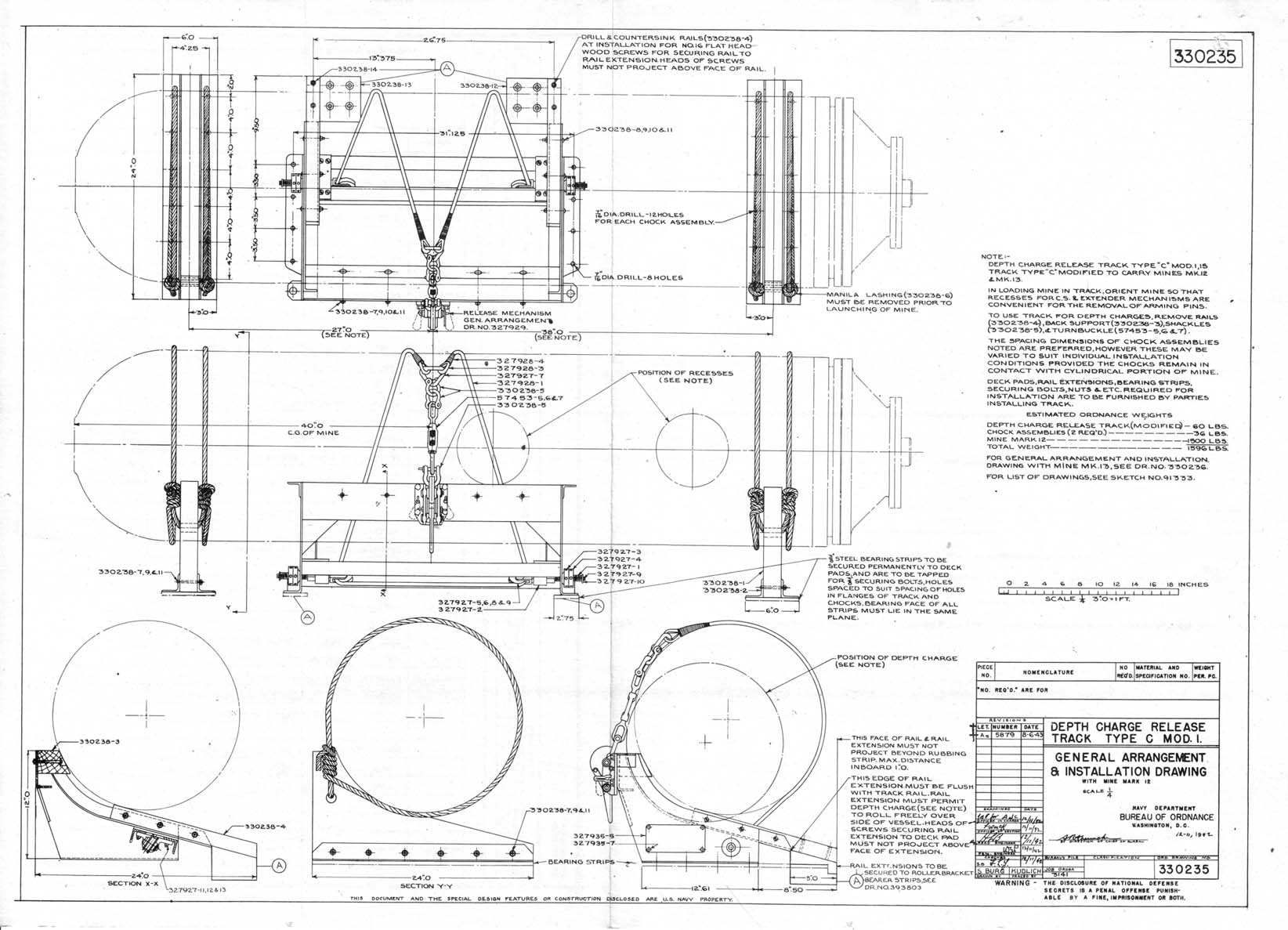
BuOrd Drawing No. 330235 - Depth Charge Release Track, Type C Mod l,
General Arrangement & installation Drawing. |
|
(C) |
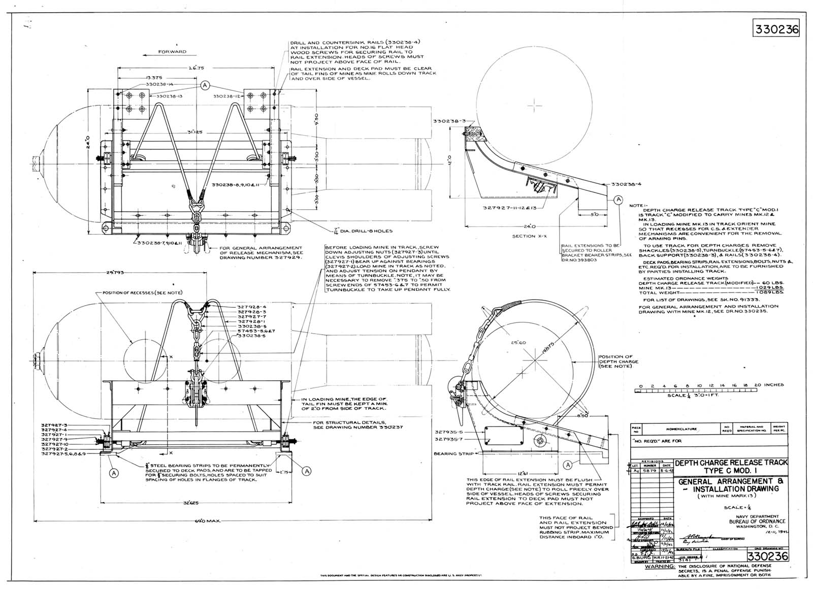
BuOrd Drawing No. 330236 - Depth Charge Release Track, Type C Mod l,
General Arrangement & installation. |
|
(D) |
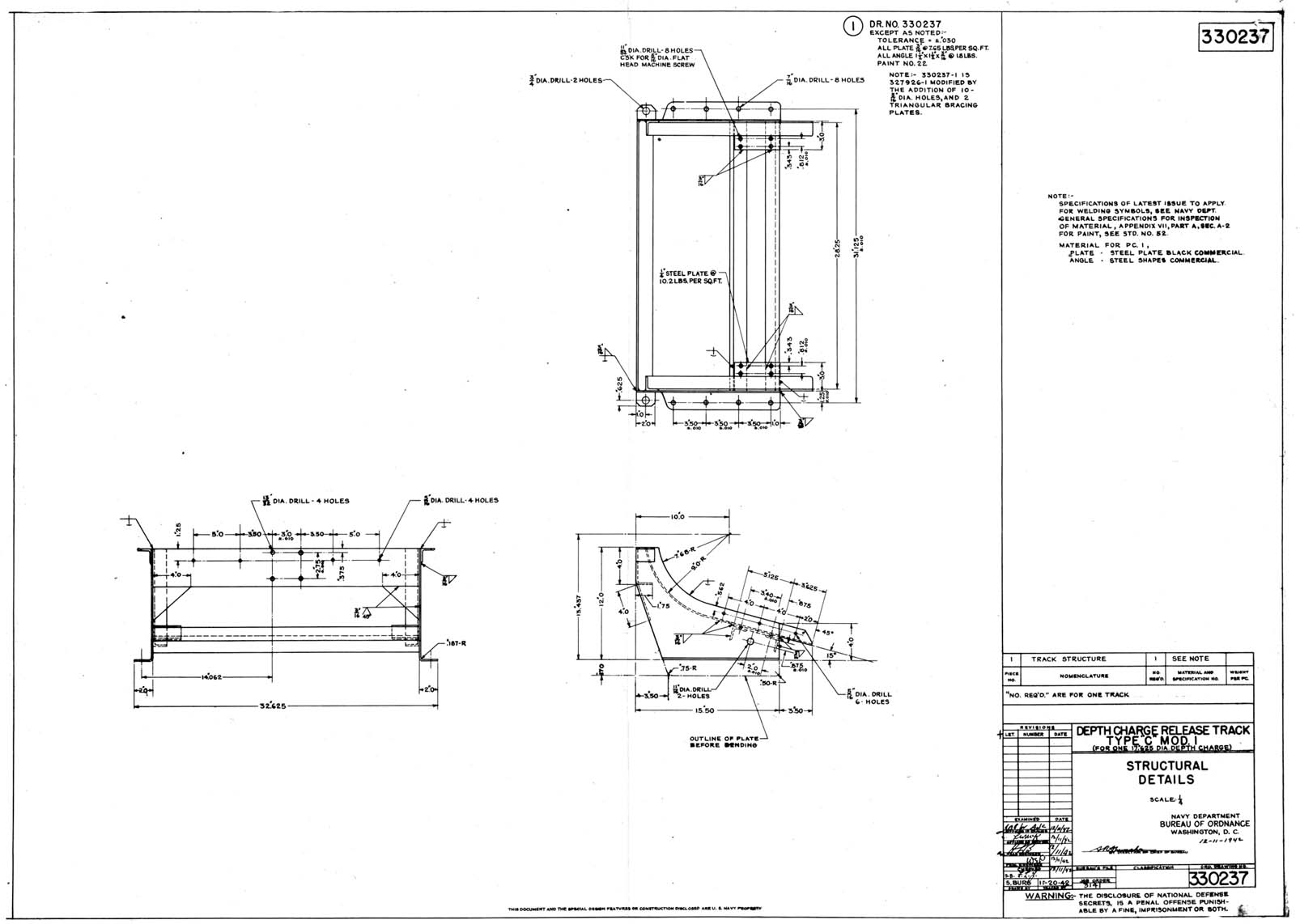
BuOrd Drawing No. 330237 - Depth Charge Release Track, Type C Mod 1,
Structural Details. |
|
(E) |
BuOrd Drawing No. 330238 - Depth Charge Release Track, Type C Mod 1,
Chock & Details. |
|
(F) |
BuOrd Drawing No. 389100 - Depth Charge Release Track, Type C Mod 1,
Installation Drawing. |
|
(G) |
BuOrd Sketch No. 108841 - Mine Track for PT Boats, List of
Drawings. |
|
(H) |
BuOrd Drawing No. 393801 - Mine Track for PT Boats, General
Arrangement. |
|
(I) |
BuOrd Drawing No. 393802 - Mine Track for PT Boats, General
Arrangement. |
|
(J) |
BuOrd Drawing No, 393803 - Lane Track for PT Boats, Installation
Drawing. |
|
(K) |
BuOrd Drawing No. 393804 - Mine Track for PT Boats, Rail Assembly and
Details. |
|
(L) |
BuOrd Drawing No. 393805 - Mine Track for PT Boats, Roller Assembly and
Details. |
|
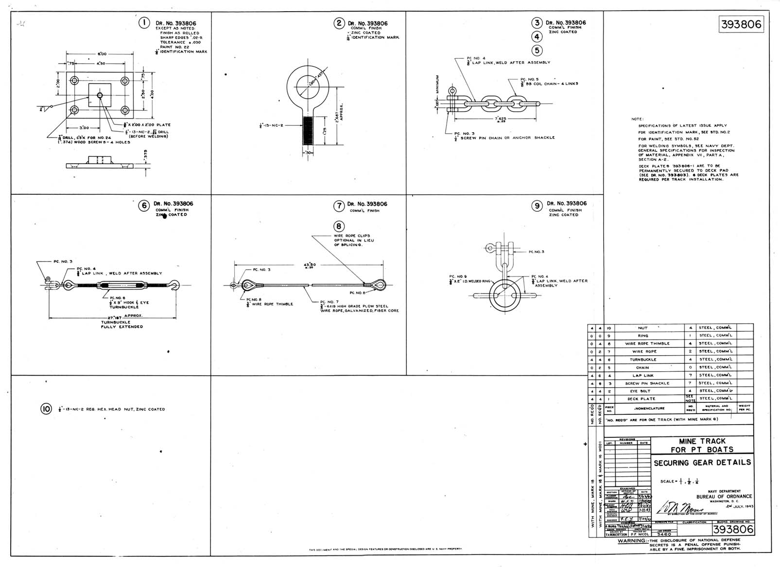
(M) |
BuOrd Drawing No. 393806 - Mine Track for PT Boats, Securing Gear
Details. |
|
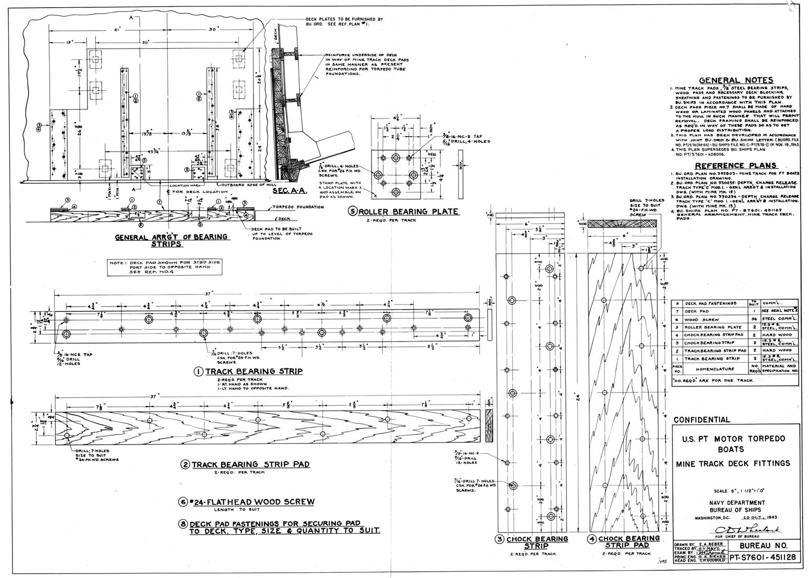
(N) |
BuShips Drawing No. PT-S7601-451128 - U.S. PT Motor Torpedo Boats, Mine
Track Deck Fittings. |
|
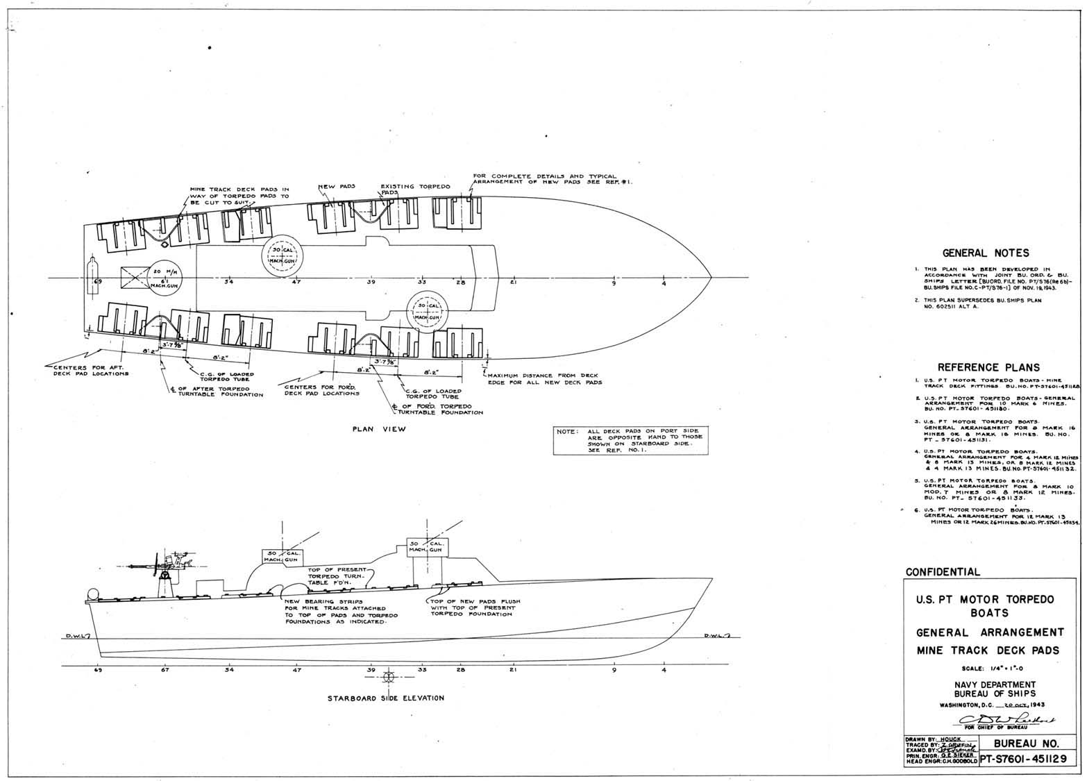
(0) |
BuShips Drawing No. PT-S760l-451129 - U.S. PT Motor Torpedo Boats,
General Arrangement Mine Track Deck Pads. |
|
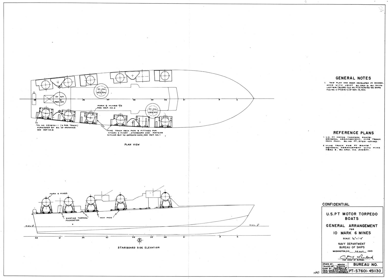
(P) |
BuShips Drawing No. PT-S7601-451130 - U.S. PT Motor Torpedo Boats,
General Arrangement for 10 mark 6 Mines. |
|
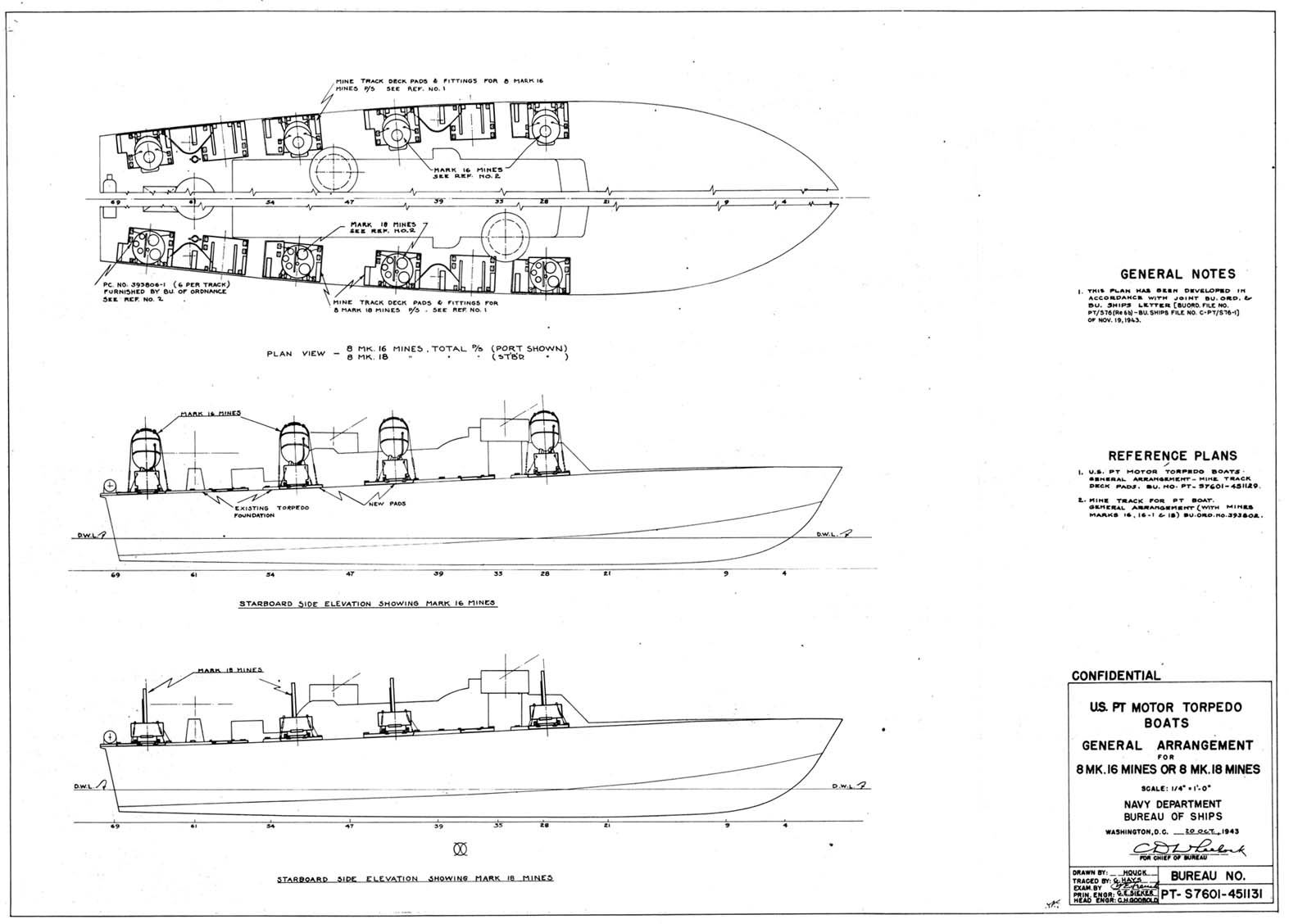
(Q) |
BuShips Drawing No. PT-S7601-451131 - U.S. PT Motor Torpedo Boats,
General Arrangement for 8 Mark 16 Mines or 8 Mark 18 Mines. |
|
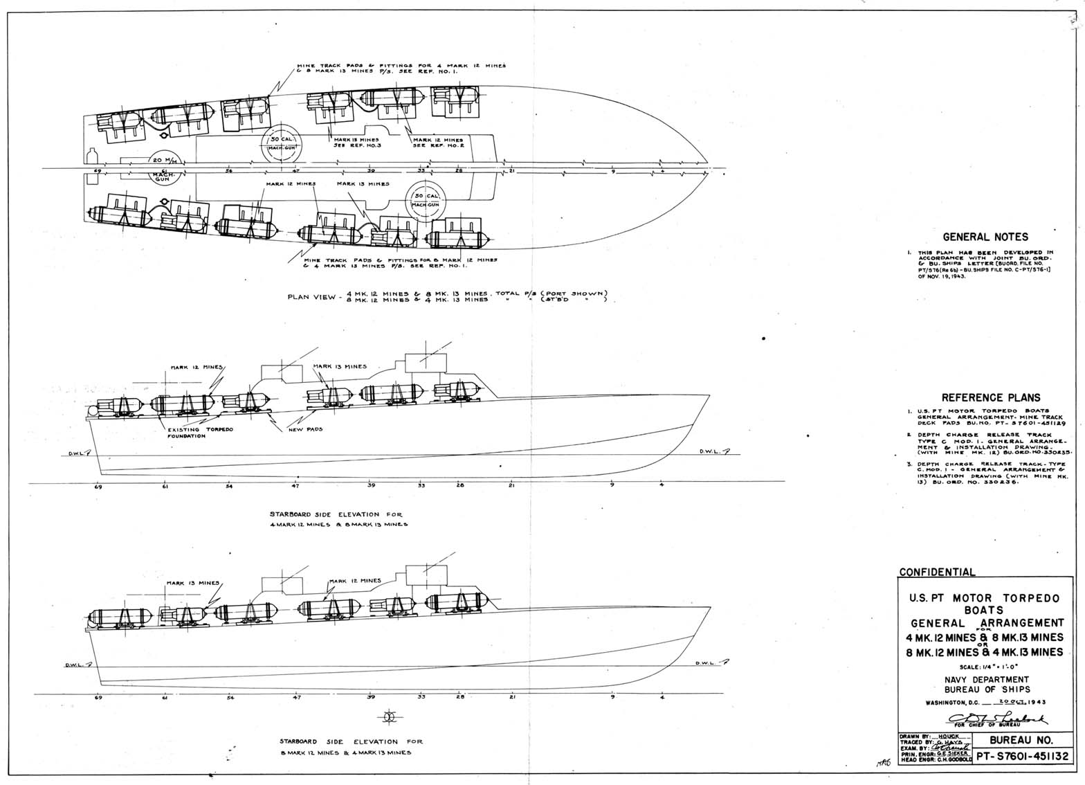
(R) |
BuShips Drawing No. PT-S7601-451132 - U.S. PT Motor Torpedo Boats,
General Arrangement for 4 Mark 12 Mines & 8 Mark 13 Mines or 8 Mark 12 Mines and 4 Mark 13 Mines. |
|
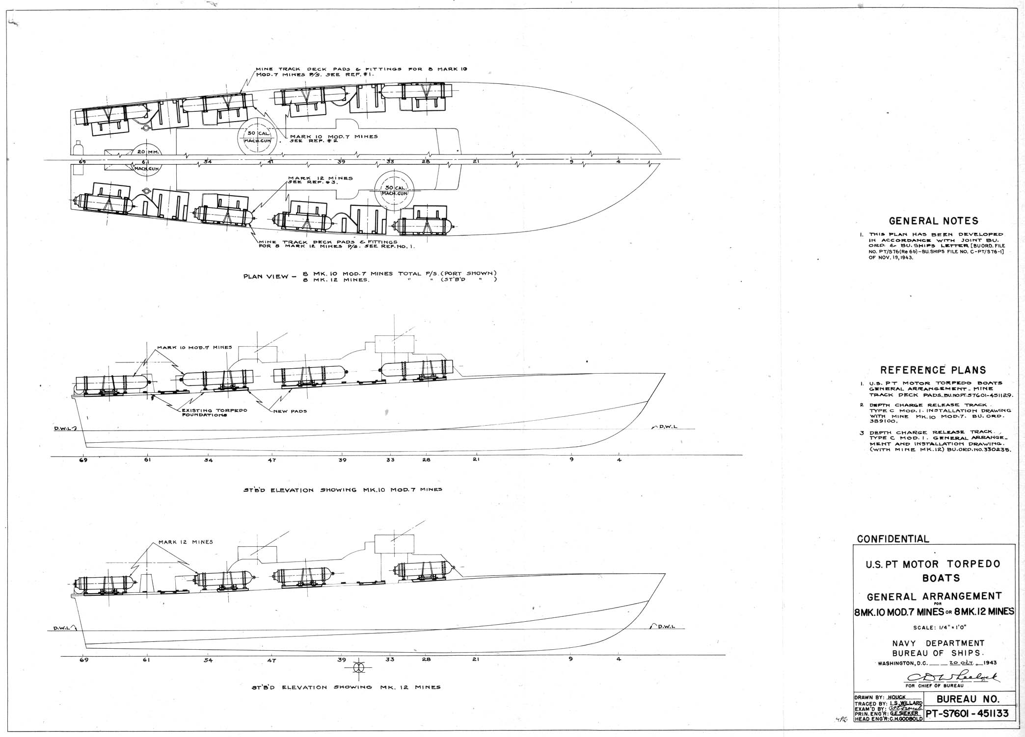
(S) |
BuShips Drawing No. PT-S7601-451133 U.S. PT Motor Torpedo Boats,
General Arrangement for 8 Mark 10 Mod 7 Mines or 8 Mark 12 Mines. |
|
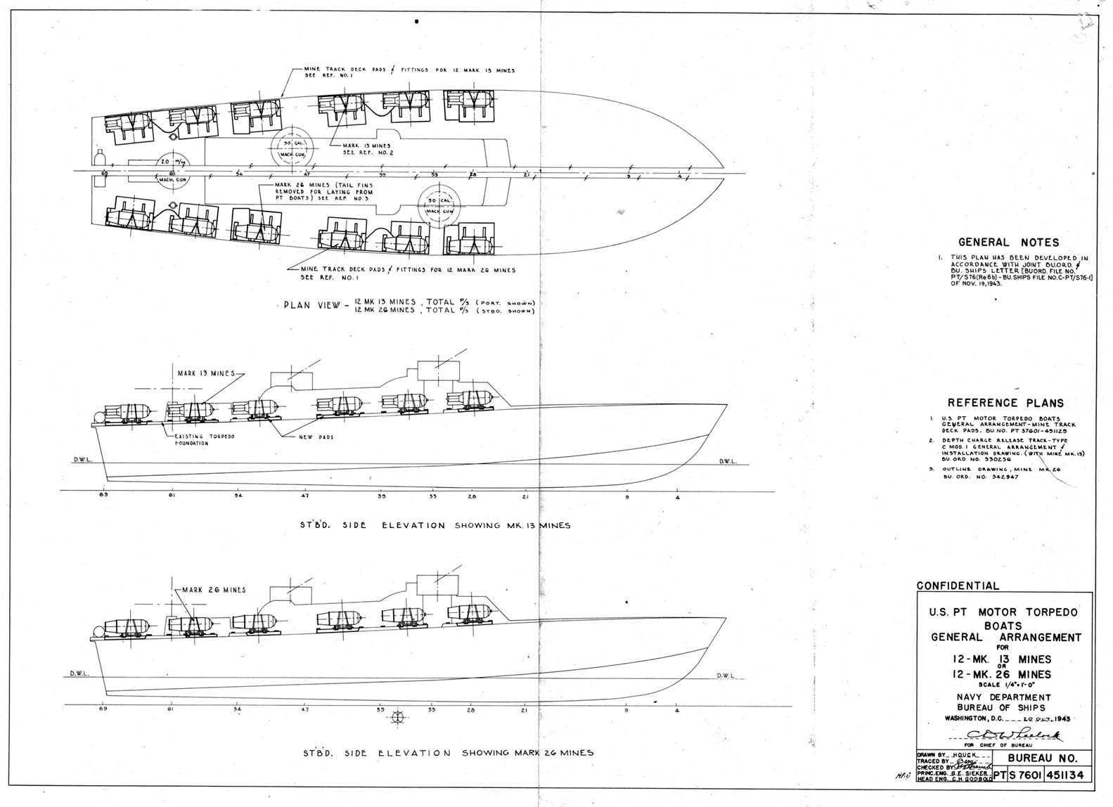
(T) |
BuShips Drawing No. PT-S7601-451134 - U.S. PT Motor Torpedo Boats,
General Arrangement for 12 Mark 13 Mines or 12 Mark 26 Mines. |
-2-
CONFIDENTIAL
|
|
Back to page top
| (Re6b) |
Cont'd - Instructions
for Laying Mines from Motor
Torpedo Boats. |
1. In order for motor torpedo boats to carry mines satisfactorily, it will be necessary to remove either the two (2) forward, the two (2) after, or all four (4) torpedo tubes or torpedo launching racks and install the following:
| |
(a) For aircraft or submarine laid mines--six (6) Depth Charge Release Tracks Type C, modified as shown by Enclosures (B) through (F), for each two (2) torpedo tubes or torpedo launching racks removed. |
| |
| |
(b) For mines designed to be laid from surface minelayers-six (6) sets of mine tracks, constructed and installed as shown by Enclosures (H) through (M), for each two (2) torpedo tubes or torpedo launching racks removed. |
It is important, in order not to affect the trim of the ship, to keep the center of gravity of the mines and minelaying gear in the same fore and aft position as the combined center of gravity of the removed torpedoes and tubes. The combined weight of twelve (12) pads as shown on Enclosure (N) will be approximately 3000 pounds. This weight will be greatly reduced if the height of the pads is the same as that of the Torpedo Launching Rack Mark l. The installed weight of mines, racks, and pads, when loaded as shown by Enclosures (P) through (T), will not much exceed the weight of the removed torpedoes and tubes. Therefore, it is important that the location and loading of the racks or tracks be an accordance with Enclosures (0) through (T). The following numbers and combinations of mines meet the conditions outlined above when two torpedo tubes have been removed:
| (a) |
Six (6) Mark 6. |
| (b) |
Four (4) Mark 10 Mod 7. |
| (c) |
Four (4) Mark 12. |
| (d) |
Six (6) Mark 13 (and Mods). |
| (e) |
Four (4) Mark 13 (and Mods) and two (2) Mark 12. |
| (f) |
Four (4) Mark 12 and two (2) Mark 13 (and Mods). |
| (g) |
Four (4) Mark 16 (and Mods). |
| (h) |
Four (4) Mark 18. |
| (i) |
Six (6) Mark 26 Mod 1 (less parachute). |
There are, of course, other combinations of the mines noted above which can be satisfactorily carried when two (2) torpedo tubes are removed. When four tubes are to be removed, it should be noted that a total of ten (10) Mark 6 mines (not 12 - see Enclosure (P)) can be carried, due to excess weight of this mine.
2. Modified Type C racks were selected for installation aboard PT boats to carry mines designed for submarine or aircraft laying because these racks are available at most advance motor torpedo boat bases and, therefore, will not necessitate the shipment of additional equipment to these bases in order to adapt motor torpedo boats, now with the Fleet, to carry and launch mines of this type. However, should Type C racks not be available they should be requested from the Bureau of Ordnance. The additions necessary for the modification of these racks are made almost entirely of wood and can be removed easily and quickly when it becomes necessary to carry depth charges in the racks. The mine tracks (Enclosures (H) through (M)) are made of standard metal stock available at most tender or repair ships. Either type of minelaying gear can be removed easily from the bearer strips (Enclosure (N)) and the original torpedo tubes replaced when minelaying or depth charge launching operations have been completed.
- 3 -CONFIDENTIAL
|
|
Back to page top
Re6b
3. When mines designed for surface laying are carried on and laid from PT boats, the minehandling gear manufactured and installed in accordance with Enclosures (H) through (M) is used, and the mines are secured in accordance with the appropriate General Arrangement Drawing. For mines designed to be laid from aircraft or from the torpedo tubes of submarines, the Type C depth charge release tracks are modified and installed as per Enclosures (B) through (F), and the mines are secured in place in accordance with the appropriate General Arrangement and Installation Drawing.
4. The wooden pads for the depth charge racks and mine tracks are to be built up to the level of existing torpedo tube or torpedo launching rack pads, whichever is already installed, in accordance with Enclosure (N). In many cases it will be necessary to tailor the new pad to fit the contour of the existing pad. If the new pads are assembled ashore, one motor torpedo boat can be equipped with a complete set of minelaying gear in approximately two days. The bearer strips (Enclosure (N)) for the minelaying gear have been designed so as to accomodate either the Type C tracks or the mine tracks. Thus, a motor torpedo boat once fitted for minelaying can quickly remove one set of gear and install the remaining set if a different type of mine is to be carried.
5. The additional pads necessary for the minehandling gear are designed so that when manufactured and installed in accordance with Enclosure (N) they will not interfere with the operation of the torpedoes or tubes if the torpedo launching equipment is reinstalled, In addition, the bearer strips for minetracks or depth charge tracks, rollers, and wooden chocks; and the steel plates (minus eye-bolts) for fastening the securing lines to the pads may be left in place without offering objectionable interference to the operation of the torpedoes or tubes. However, if no minelaying or depth charge launching operations are anticipated in the immediate future, the added weight (approximately 250 pounds per pad) of the additional wooden pads will prove objectionable. In this case, the pads should be REMOVED and held in storage until needed again for a similar operation.
MARK 6 and MARK 16 MOD 1 MINES
6. Mark 6 and Mark 16 Mod 1 mine assemblies will probably be delivered to minelayers ready for planting with the exception of H-6 horns and washers, H-4 horns and guards, and extender soluble washers if these are to be used. Routine inspection and minor repairs to remedy damage incurred during loading operations should be made aboard the motor torpedo boat.
7. To prevent probable damage to H-horn assemblies during mineloading operations, the H-4 horns and guards should not be installed until the mines are in place on the tracks and the securing lines on the mine case and anchor have been properly adjusted. The H-6 horns and washers should not be installed-until just prior to the minelaying operations (see paragraph 12(e) below).
8. Upon completion of the mineloading, the mine assembling (with exception of H-6 horns and H-6 soluble washers) should be completed. Before getting underway for minelaying, the remaining assembly operations and the
- 4 -CONFIDENTIAL
|
|
Back to page top
(Re6b)
necessary tests for electrical grounds (reference (b), page 78) should be completed and the 5th wheel pin should be removed from the mine anchor.
9. Three types of soluble washers are available for use in K-type mine firing mechanisms. They are distinguished by their colors, which are; blue, pink, and green. Blue washers dissolve in five to fifteen minutes after the mines are planted; pink washers dissolve in fifteen to forty-five minutes; and green washers in three to six hours. The delay period of an individual washer is determined partially by the temperature of the water in which a mine is planted, cold water increasing the delay and warm water decreasing it. The delay periods noted above are in still water and will decrease when mines are planted in areas where currents prevail.
10. Mark 6 and Mark 16 Mod 1 mines will probably be delivered to the motor torpedo boat with soluble washers installed in the firing mechanism safety switches. However, if mines are exposed to excessive moisture after the washers are installed and before the mines are planted, as will probably be the case when carried on the decks of PT boats, the washers may disintegrate sufficiently to allow the firing mechanism to become armed as soon as the mines are submerged to the operating depths of the firing mechanism safety switches. Therefore, the condition of the soluble washers should be checked (reference (b) page 79) a short time before the mines are laid.
11. If soluble washers are to be used on extenders, they should be installed at the assembly depot or aboard the PT boat prior to getting underway.
12. Shortly (not to exceed 30 minutes) before the estimated time of launching the mines, the following must be done:
| (a) |
Remove securing lines from mine cases and anchors. |
| (b) |
Remove safety nuts from extender mechanisms. |
| (c) |
Remove the safety switch covers from the K-mechanisms. |
| (d) |
Check conditions of soluble washers in K-mechanisms (reference (b) page 79). If a washer shows signs of disintegration a new one should be installed. |
| (e) |
Install the H-6 soluble washers and H-6 horns on the antenna floats. |
| (f) |
See that 5th wheel pin has been removed. |
13. Immediately before each mine is laid, the short-circuit clip must be removed from the copper plates of the K-mechanism by the officer in charge of the minelaying crew.
MARK 18 MINE
14. Unlike the Mark 6 and Mark 16 Mod 1 mines, the Mark 18 mine will probably be delivered to the PT boat completely assembled and ready for planting except for certain safety devices which must be removed prior to planting. Before being brought aboard, all mines should be given the necessary inspection and field operational tests by the mine assembly officer in accordance with reference (i).
- 5 -CONFIDENTIAL
|
|
Back to page top
(Re6b)
15. The choice of the proper combination of soluble washers to be used will depend upon planting conditions and will be directed by the officer in charge of the mining operation.
16. In an offensive field, duds are considered preferable to prematures as the latter will reveal the presence of the field to the enemy. Conversely, in a defensive field, prematures are considered more desirable than duds as they will reveal defects in the field and will permit corrections in order to alleviate this condition. Therefore, in offensive mining, extenders should be fitted with soluble washers, if practicable, so that they will be held in the retracted position until after the clock delay mechanisms have armed. If the firing circuit closes prematurely, the detonator will fire in the retracted position and the mine will be a dud. Mines being prepared for a defensive field should be fitted with extender soluble washers whose delay period is short enough to permit the extenders to operate before the clock delay mechanisms operate; or, extender soluble washers should be omitted. In this way, premature closing of the firing circuit will cause the detonator to fire in the extended position and the main charge will explode.
17. Just prior to the loading of the mine tracks, the wooden washers in the clock starters rust be replaced with soluble washers, and the wooden washers in the extenders must be removed and may or may not be replaced by soluble washers as set forth in paragraphs 15 and 16. If the wooden washers are not removed, the mechanisms will remain locked in the unarmed position and the mines will be duds. Cracked or chipped soluble washers should not be used as they may allow premature operation of the mechanisms in which they are installed. Instructions for installing the soluble washers are given in reference (i). Covers for the extender and clock starter mechanisms with REMOVE BEFORE LAUNCHING tags attached should be placed on these mechanisms to prevent the action of the sea from causing the soluble washers to disintegrate prematurely
18. When loading the tracks, the Mark 18 mine should be oriented so that the arrow on top of the mine case points outboard. The mines should be secured in place in accordance with Enclosure (I).
19. Immediately before launching the following procedure must be carried out:
| (a) |
Remove securing lines. |
| (b) |
Remove the tag and cotter pin from the drag plate release mechanism. |
| (c) |
See that upper edge of drag plate is secured to the search coil housing with a loop of 20 pound cord. |
| (d) |
Remove the "U" clamp from the top edge of the drag plate. |
| (e) |
Remove covers from the clock starter and extender mechanisms. |
| (f) |
Inspect the soluble washers in clock starter and extender mechanisms to insure that they are in good condition. Washers showing signs of disintegration should be replaced. |
20. To complete the laying procedure on mines of this type it will be necessary to withdraw the securing latches from the inboard anchor wheels and then manhandle the mines over the side.
- 6 -CONFIDENTIAL
|
|
Back to page top
(Re6b)
MARK 10 MOD 7 MINE
21. The Mark 10 Mod 7 mine is a Mark 10 Mod 3 submarine-launched mine modified for planting from surface craft. Reference (c) together with instructions for conversion of a Mark 10 Mod 3 to a Mark 10 Mod 7 will be issued to mine assembly depots when the Mark 10 Mod 3 mine is released for service.
22. Mark 10 Mod 7 mines will be made up at assembly depots or aboard specially equipped ships and will be delivered to laying vessels in "ready" condition. The only preparations for planting to be performed aboard the-laying vessel will be the removal of safety devices and the sea lashings from the wooden end chocks just prior to launching.
23. An assembled mine should be lifted by a sling placed around the mine assembly at its center of gravity (approximately 42-1/2 inches from the base of the anchor). It should be noted that the cases of these mines are comparatively soft, and care should be taken to avoid deforming them. When handling an assembled mine the Mark 3 Mod 4 release mechanism safety pin must always be kept in place until the mine is placed in a rack for planting. If it is not, the case and anchor may separate prematurely. To prevent the possibility of a mine becoming armed prematurely, safety pins in the clock starter, extender, and the Mark 3 Mod 4 release mechanism must be kept in place at all times until the mine is prepared for planting (see paragraph 25).
24. Mark 10 Mod 7 mines should be installed in the racks in accordance with Enclosure (F). Prior to the loading the safety bar should be removed from each mine. All safety pins are left in place on extenders, clock starters, and Mark 3 Mod 4 release mechanisms.
25. Just prior to launching, the safety pins must be removed from the clock starters, extenders, and Mark 3 Mod 4 release mechanisms and the sea lashings must be removed from the wooden chocks. Thus in order to lay the mines after the aforementioned operation has been completed, it is only necessary to operate the release mechanism of the Type C Mod 1 depth charge release tracks.
MARK 12 MINE
26. Mark 12 mines will be made up as fixed ammunition at assembly depots or aboard specially equipped vessels, and will be issued to planting vessels in "ready" condition. The only operations on the mines aboard the PT boat will be the removal of safety appliances and the sea lashings from the wooden end chocks.
27. Assembled Mark 12 mines should be kept in their shipping crates (if these are available) until they are loaded aboard the PT boats. It should be noted that the cases of these mines are comparatively soft, and care should be taken to avoid deforming them. All handling gear should be applied to the crates to avoid injuring the mines. Crated mines may be stacked (in horizontal position) on wooden two-by-four studs, and may be stacked three deep if necessary, with wooden studs between each crate.
- 7 -CONFIDENTIAL
|
|
Back to page top
(Re6b)
28. When removing a Mark 12 mine from a crate, take off the crate cover and the removable (after) end. Loosen the bolts which hold the ring on the nose of the mine. Be sure that safety pins are in place on clock starter and extender mechanisms and that the cords on the pins are prevented from fouling. Remove the safety bar screw and the safety bar. Place a sling around the mine case at its center of gravity (approximately 40 inches from the nose) and lift it from its crate. A mine may also be lifted by a line passed through an eye-bolt screwed in the nose or the tail of the mine case.
29. Mark 12 mines are secured in the racks as shown by Enclosure (B). Precaution must be taken to see that the clock starter and extender safety pins are not injured or removed. This will maintain the usual safety features of the mine. Immediately before a mine is planted, its sea lashings must be cast off and the safety pins must be removed from the clock starter and extender.
| NOTE: |
If the retainer caps of the clock starter and extender are not fitted with retainer cables, they will be forced off by the springs beneath them with sufficient force to injure personnel unless caution is observed in removing the safety pins. |
MARK 12 MOD 1 MINE
30. Mark 12 Mod 1 mines, without parachute attachment, can also be laid satisfactorily from deck racks of PT boats. These mines when converted for surface laying will differ from Mark 12 mines by having a different clock starter and extender mechanism. Mark 12 Mod 1 mines so converted may have Mark 1 Mod 1 or Mark 1 Mod 4 clock starters and Mark 12 Mod 1 or Mark 12 Mod 4 extenders.
31. The Mark 1 Mod 1 clock starter is similar to the Mark 1 except for the outer portion of the mechanism. The ball lock parts are replaced by a large metal washer which rests on a shoulder on the piston rod and is held in place by a wing nut. A wooden washer is placed in the clock-starter during shipment and storage to lock it in the safe position. This washer must be replaced by a soluble washer before the mine is planted. A metal cover screws onto the outer portion of the mechanism to protect the soluble washer.
32. The Mark 12 Mod 1 extender differs from the Mark 12 in the same way that the Mark 1 Mod 1 clock starter differs from the Mark l. On the Mark 12 Mod 1 extender the ball lock parts are replaced with soluble washer parts similar to those of the clock starter. The same type of wooden washers are used in both mechanisms.
IMPORTANT: Wooden washers must be kept in place in clock starters and extenders in assembled mines until the mines are prepared for planting. If they are not, and a mine is dropped accidentally in friendly waters, or stored in a magazine which has to be flooded, the mechanism may operate and arm the mines. The wooden washers are to be removed and replaced with soluble washers immediately before the mines are prepared for planting.
- 8 -CONFIDENTIAL
|
|
Back to page top
(Re6b)
If the wooden washers are not removed at this time, the mines will be duds, as the washers will lock the clock starters and extenders in safe position.
33. The Mark 1 Mod 4 clock starter is similar to the Mark 1 except that a spacer sleeve, secured by a cotter pin before planting, takes the place of the ball lock assembly. When the mine is secured in a Type C Mod 1 track, an arming wire replaces the cotter pin. Before the mine is dropped, the arming wire is withdrawn by hand and the clock starter is then free to operate. A transparent cover is supplied with this mechanism to protect its outer parts until the mine is prepared for planting.
34. The Mark 1 Mod 4 clock starter may be modified for use as soluble washer controlled device. The delay arming accessories in this case will consist of one of three soluble washers (pink, 1 day dissolving time; yellow; 2 days; and blue, 3 days), a knurled nut, and a cotter pin. When a soluble washer is to be used instead of an arming wire, the spacer sleeve is removed from the clock starter, the soluble washer is slipped over the piston rod of the mechanism, and the nut is screwed on the outer end of the piston rod and locked by the cotter pin.
35. The Mark 12 Mod 4 extender is similar to the extenders (Mark 12 and Mark 12 Mod 5) installed in unmodified Mark 12 mines except that a spacer sleeve secured by a cotter pin or arming wire replaces the ball lock. As in the Mark 1 Mod 4 clock starter mechanism, arming wires release the extender mechanism for action when the mine is planted. The Mark 12 Mod 4 extender may also be converted for use as a soluble washer controlled device with delay arming accessories.
36. If soluble washers are to be used, they should be installed as soon as possible prior to the time when the mines are to be planted. To install soluble washers in a Mark 1 Mod 1 clock starter or a Mark 12 Mod 1 extender:
| (a) |
Unscrew the mechanism cover and remove the nut, metal washer and wooden washer from the mechanism cap. |
| (b) |
See that the mechanism is reasonably dry, and that the soluble washer to be used is not cracked and is firm and hard. |
| (c) |
Place the soluble washer over the piston rod and seat it on the mechanism cap. |
| (d) |
Place the metal washer on top of the soluble washer and secure it by screwing the wing nut down on the piston rod until it takes up against the metal washer. The metal washer should be seated firmly on the piston rod shoulder or on the soluble washer. |
| (e) |
Replace the mechanism cover, screwing it firmly in place. |
| |
|
NOTE: |
Use hand pressure only in tightening wing nuts, and do not exert sufficient torque on a clock starter wing nut to twist the piston rod and thus possibly damage the diaphragm. |
37. If converted Mark 12 Mod 1 mines are fitted with Mark 1 Mod 4 clock starters and Mark 12 Mod 4 extenders, remove the covers of these mechanisms
- 9 -CONFIDENTIAL
|
|
Back to page top
(Re6b)
and substitute arming wires for the safety cotter pins with which the mechanisms are fitted during storage and shipment. Be sure the spacer sleeves are properly placed on the piston rods so that the arming wires will prevent motion of the piston rods of the mechanism, then secure the arming wires in place with two Fahnestock clips on each wires. The arming wires should then be removed by hand immediately before the mines are planted.
MARK 13 AND MARK 26 MOD 1 MINES
38. Mark 13 mines (and Mods) and Mark 26 Mod 1 mines (less parachute) are secured to the Type C Mod 1 racks (without wooden chocks) in accordance with Enclosure (C). These mines are fitted with clock starters and extenders equipped to take arming wires. Consequently, information given above for Mark 12 Mod 1 mines, when equipped with clock starters and extenders of this type, will be applicable to the Mark 13 and Mark 26 Mod 1 mines. It should be noted that the Mark 13 Mod 5 mine may be handled similarly to the Mark 13 mine but must be protected from temperatures above 110° F. In addition, the microphone in the tail plate of the Mark 13 Mod 5 mine must be protected against cutting of or damage to the rubber cover.
GENERAL INFORMATION
39. In addition to the minelaying gear described above, mines designed for laying from 21 submarine torpedo tubes and aircraft mines whose cylindrical body exceeds forty-four (44) inches in length, have been carried by and launched from the Torpedo launching Rack Mark l. When this rack is used for minelaying the mines are secured in the same manner as torpedoes. Whenever possible the mines should be oriented in the rack so that the clock starter and extender wells face inboard.
40. Preparation of the mines prior to their delivery to the motor torpedo boat bases or tenders will be the responsibility of the mine detail, mine depot, or mine assembly base concerned. In case additional technical information of the mines is required, this information can be obtained from the activity supplying the mines.
41. It will probably be necessary to carry out the immediately before planting" operations for the mines noted above at night and without the aid of lights. Therefore, it is recommended that several daylight and at least one night drill of these operations be conducted by the minelaying crew prior to the ship's getting underway.
42. During trials conducted on equipment shown by Enclosures (A) through (T) and the Torpedo Launching Rack Mark 1, mines were laid satisfactorily from PT boats at speeds varying from six to thirty knots. However, except in extreme emergency, low laying speeds are preferable.
* * * * * * * * * * * * * * * * * * * * * * * * * * * * * * * * * * * *
HVS/EAJ
CONFIDENTIAL
- 10 -
|
|
Originally scanned and formatted by Tracy White, Researcher@Large. Formatting code copywritten © and may not be reproduced without the permission of R@L or PT Boat World. |
|